
NI Multisim is industry standard SPICE simulation and circuit design software for analog, digital, and power electronics in education and research. I have used NI Multisim for design, analysis, and simulation of basic and complex analog circuits. I am comfortable with designing circuits with the intent to obtain simulated/theoretical values of circuit configurations. For the majority of the projects listed below, after using NI Multisim I built the circuit using physical components and a breadboard and/or soldering.
Hey y'all, I am Yusef Ibrahim!
Analog circuit design, filter design, building circuits, simulation and testing.
Analog circuit design, filter design, building circuits, simulation and testing.
Analog circuit design, filter design, building circuits, simulation and testing.
NI Multisim is industry standard SPICE simulation and circuit design software for analog, digital, and power electronics in education and research. I have used NI Multisim for design, analysis, and simulation of basic and complex analog circuits. I am comfortable with designing circuits with the intent to obtain simulated/theoretical values of circuit configurations. For the majority of the projects listed below, after using NI Multisim I built the circuit using physical components and a breadboard and/or soldering.
Bandpass Resonance Filter Project
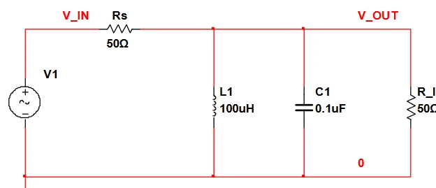
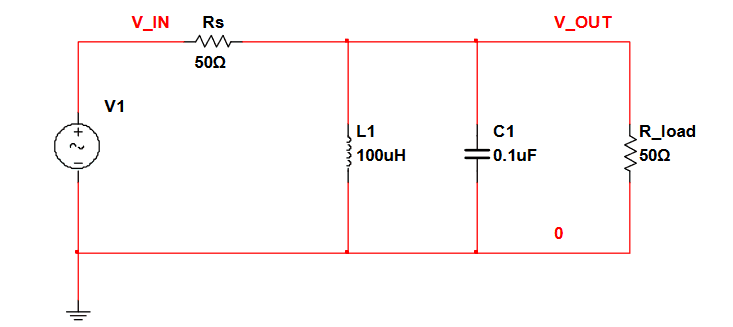
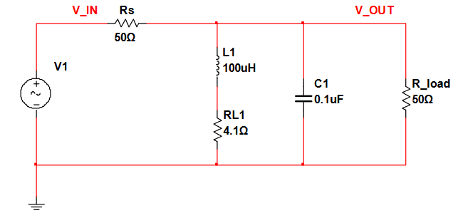
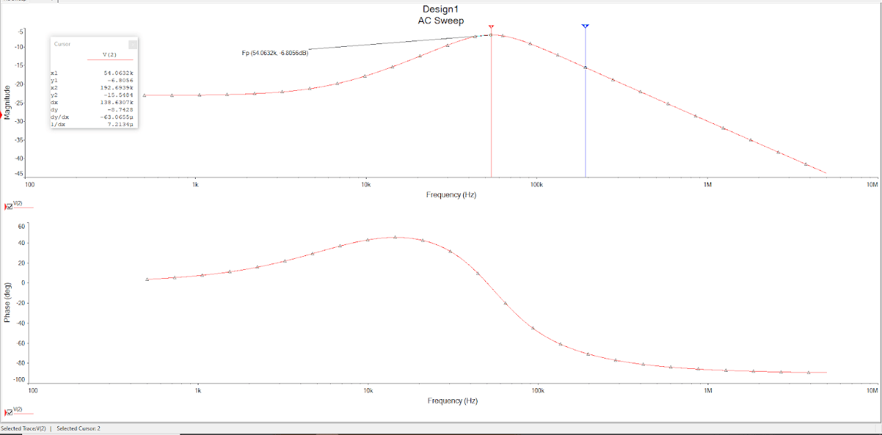
At resonance, the circuit will experience a maximum voltage gain and maximum total current. The series model of resonance is based on a voltage source in series with a singular resistor, capacitor and inductor. The parallel model is based on a current source in parallel with a singular resistor. capacitor, and inductor. The main objective of this project was to to design and analyze a parallel resonant filter circuit using ideal and non-ideal component models, determining the resonant frequency, loaded circuit Q and voltage gain.
Mesh/Nodal
Mesh and nodal analysis
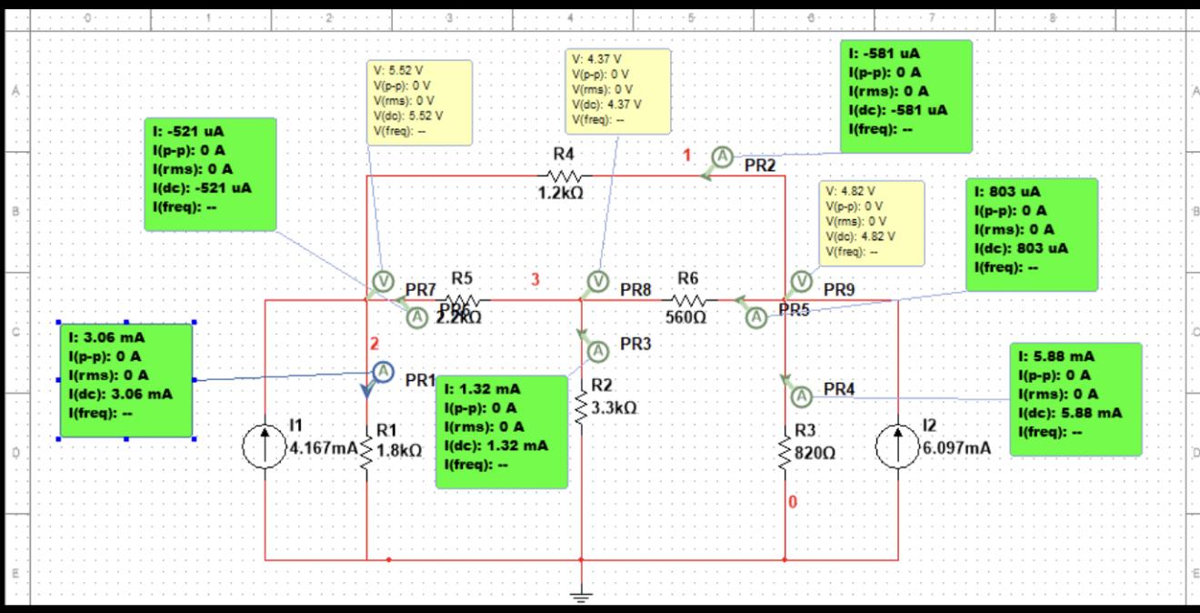
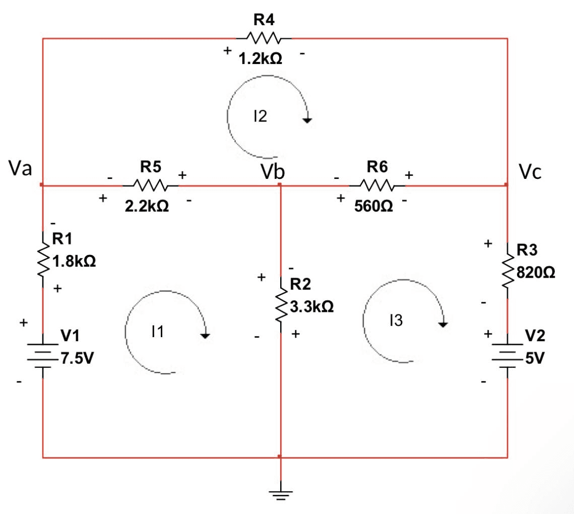
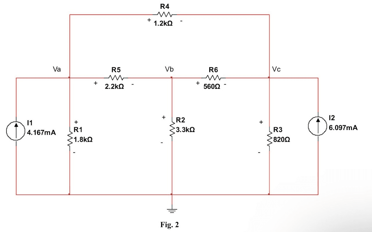
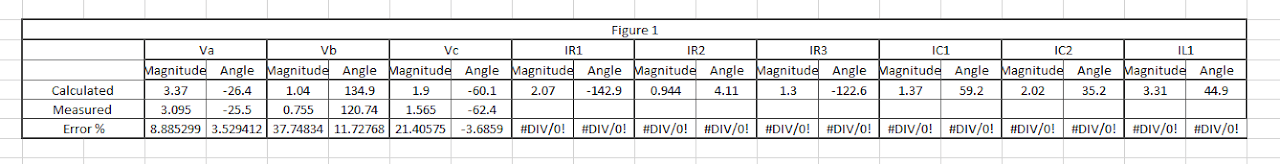
In the first figure, mesh analysis was employed to ascertain the currents flowing through the circuits. This involved not only calculating the values but also measuring them by constructing the circuit in the lab. In Figure 2, nodal analysis was utilized to determine the voltages coursing through the circuits. This process again included calculating the values, but instead of measuring them, we simulated the circuit due to the impracticality of constructing it with the provided numerical data.
Let’s
Collaborate